In order to improve my R/C flying skills and also learn how to fly helicopters I got a AeroFly flight simulator for Windows a few years ago. This flight sim allows you to fly planes and helicopters with your own R/C transmitter which greatly helps training for the real thing.
The status of the driver (as of Nov 2002) is that is basically works. However when running with OpenGL the results get very erratic on my system (Athlon 1.2 GHz, GeForce2 GTS). I suspect this is caused by the nvidia OpenGL kernel driver not being interruptible or holding long-time locks so that the device driver is unable to properly time the interrupts. This makes it pretty much unusable for my purposes. :-(
I've briefly thought about porting the driver to RTLinux or RTAI but instead decided to go with a PIC interface instead.
Fundamentals
The software comes with an adapter cable that connects the R/C transmitter (I'm using a Graupner/JR mc16/20) with the serial port of the computer and which transmits/converts the PWM signals from the transmitter to the serial port. (PWM stands for Pulse Width Modulation or Proportional Width Modulation, depending on who you ask.)
The transmitter's high-frequency modulator is physically disconnected during simulation, so you have to open the transmitter and re-connect some cables to switch to 'real' flight mode. Or you install a switch but that (in Germany) voids your operating license and could be considered dangerous in-flight. Just imagine accidentally switching to simulator mode while hovering...
Here's a small diagram of the adapter that I found here:
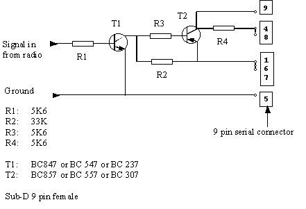
Not being very electronics literate I can't tell exactly what the adapter does other than that it amplifies the PWM signal. This is then routed to various of the modem status lines of the serial port (lines 4,8,9). The device is powered from the serial port so you don't need an additional power supply.
The pins of the serial port are as follows:
| Pin | Name | Description |
|---|
| 9 | RI | Ring Indicator |
| 4 | DTR | Data Terminal Ready |
| 8 | CTS | Clear To Send |
| 1 | CD | Carrier Detect |
| 6 | DSR | Data Set Ready |
| 7 | RTS | Request To Send |
| 5 | GND | Signal Ground |
You can find a good intro to PPM and PWM modulation (there's a link to the english version at the top) and some very helpful timing diagrams.
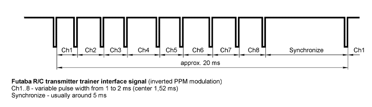
As can be seen in the timing diagrams, a sequence consists of a sync pulse of a given length and one pulse of around 1000 to 2000 usec for each channel.
Linux Kernel Module
Having figured out what comes out of the adapter the next task was to get this data into the computer. So I first wrote a simple user-land test program that polled the modem-status lines for changes of the RI line and recorded the times. This kinda-sorta worked: it got correct results but frequently lost sync which was mostly due to scheduling issues. Increasing the scheduling priority improved it somewhat but didn't leave much room for anything else on the CPU (a Pentium II, 400 MHz).
After grepping in the serial.c source I discovered the TIOCMIWAIT system call which allows a user-land program to sleep until a certain change in the modem-status line occurs. This brought down the CPU load to acceptable limits but still had some timing issues since interrupt response times aren't guaranteed.
To resolve these problems (and as an exercise in kernel hacking) I decided to write a loadable module that makes the R/C transmitter look like a regular 8-axis joystick. It does this by implementing a joystick input device so you must have both input device and joystick support, either as a module or compiled into the kernel.
For reasons I don't yet fully understand the handler is only called for the rising edge of each pulse. It might have to do with the way the APIC or the SIO handles interrupts. But it actually made things easier for me since the only thing I had to do was to get the timestamps for these events and keep track of which channel was current. The sync pulse is easily identified since it's the only one over (way over) 2000 usec length. The load the module places on the system is negligible.
The driver attempts to calibrate itself by recording the longest/shortest pulse encountered and using them as upper/lower bounds. The input driver takes care of most of that as well as filtering out noise.
Please download the latest version and give it a try if you're into this sort of thing and tell me if it works for you or not. The test app sdl-test requires SDL).
To compile simply do the following:
$ tar xvzf aerofly.tar.gz
$ cd aerofly ; make
This should get you aerofly.o and sdl-test. Then as root:
# modprobe input
# modprobe joydev
# insmod ./aerofly.o
The driver assumes your transmitter is connected to the first serial port (ttyS0 aka COM1). If it's not you can give a port=X argument to the insmod command where X is the port number from 0...3. The port number determines the I/O base address and the IRQ that will be used (see table).
| Port | tty | I/O base | IRQ |
|---|
| 0 | ttyS0 | 0x3f8 | 4 |
| 1 | ttyS1 | 0x2f8 | 3 |
| 2 | ttyS2 | 0x3e8 | 4 |
| 3 | ttyS3 | 0x2e8 | 3 |
You can check the settings of your serial port by running:
$ setserial /dev/ttyS0
/dev/ttyS0, UART: 16550A, Port: 0x03f8, IRQ: 4
If your serial port uses different I/O base or IRQ setting you can specify them directly using the iobase=X and irq=Y arguments to the insmod command. Please use either port or iobase / irq.
Parameters
port=X    Port number where adapter is installed, determines I/O base and IRQ
iobase=X  I/O base address of serial port
irq=X     IRQ number of serial port